GETTING
STARTED
POWERING
THE METER
1. Set the S1 dip switches according to Table 2-3.
2. Connect input signal (refer to Section 3.2 for commonly used
sensors).
3. Connect the proper voltage to the power screw terminal (TB1).
The meter shows the programmed function (default is rAtE mode).
AC
Power Detail Table 3-1
|
Connector
|
Description
|
Europe
|
USA
|
|
TB1-1
|
AC
Line Connection
|
Brown
|
Black
|
|
TB1-2
|
AC
Neutral Connection
|
Blue
|
White
|
|
TB1-3
|
AC
Earth Ground Connection
|
Green/Yellow
|
Green
|
Signal
Connector Table 3-2
|
Connector
|
Description
|
|
TB2-1
|
Excitation
Output (5 V, 8.2 V or 12.4 Vdc)*
|
|
TB2-2
|
Signal
Input*
|
|
TB2-3
|
Signal
Return
|
|
TB2-4
|
Reset
Input (active when tied to TB2-3) |
|
TB2-5
|
External
Gate Input** |
|
TB2-6
|
Backup
Battery (positive connection, use TB2-3 for return) |
* Refer
to Table 2-3, S1 DIP Switch Positions.
** Normally used in timing applications, not rate applications.
Refer to Section 5.2 (Stopwatch in the Totalize Mode) for more information
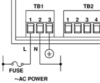
Figure 3- 1. Electrical Connection for AC
Power
CONNECTING
TO COMMONLY USED SENSORS
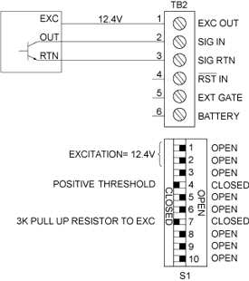 Figure
3-2
3-Wire Sensor w/NPN Open Collector Output
|
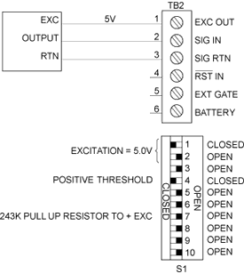
Figure 3-3
TTL/5 V CMOS Output
|
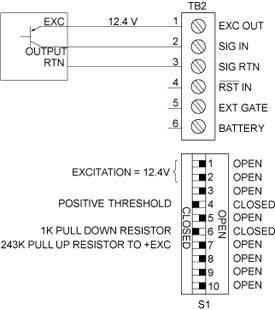
Figure 3-4
3-Wire Sensor w/PNP Open Collector Output
|
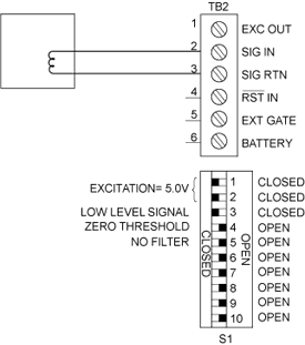
Figure 3-5
2-Wire Magnetic Pickup
(Low Level Signals)
|
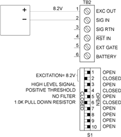
Figure 3-6. 2-Wire NAMUR Sensor
|
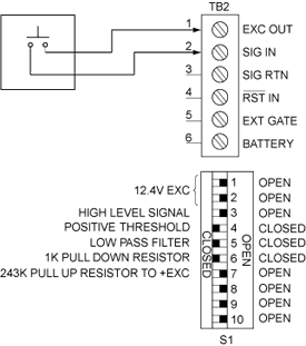
Figure 3-7. 2-Wire Contact Closure
|
|